
TL;DR
I share here, how I designed and built my custom version of mechanic flipper based on solenoid. This is my starting point for the project of real wooden pinball machine v2.0.
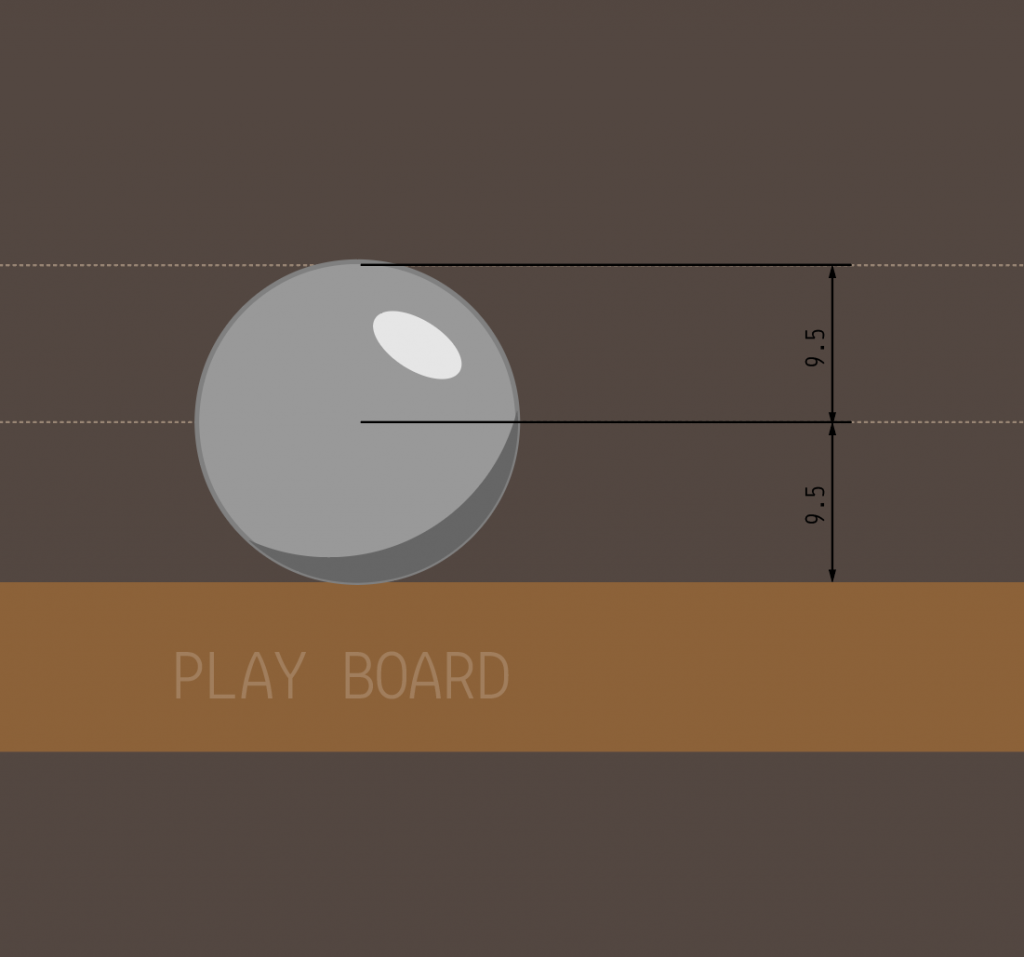
After a lot of articles read and tones of resources checked in the Internet I started building my own flipper for a pinball machine I had in mind since years. I started with some 2D drawings in Adobe Illustrator to get the idea drawn. First the metal ball I bought. The ball I will use for my machine is smaller than normal one and has diameter of 19 mm.
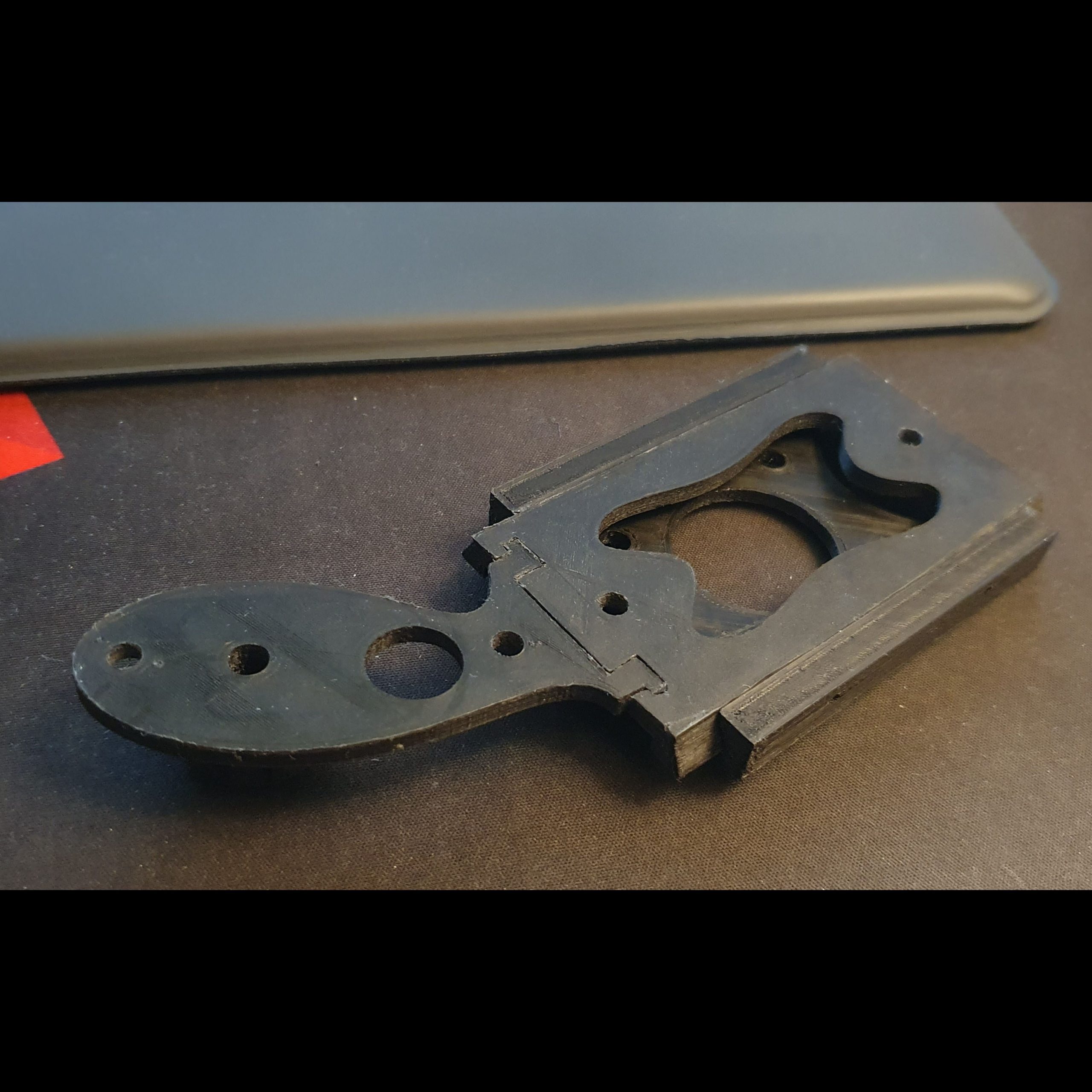
Then I started planning the flipper, size and shape, which can be then easily printed on my 3D printer and which can be connected with metal core.
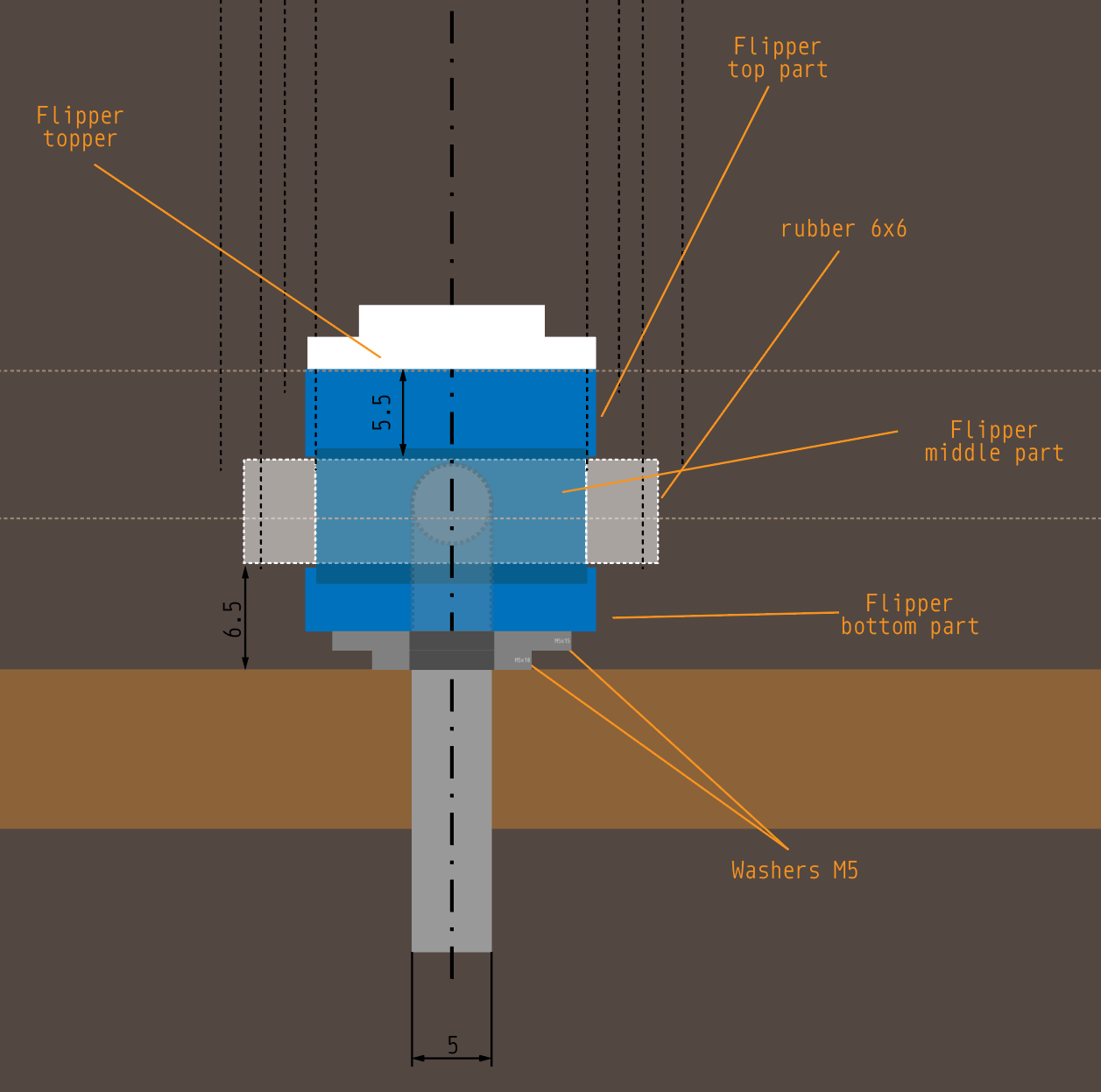
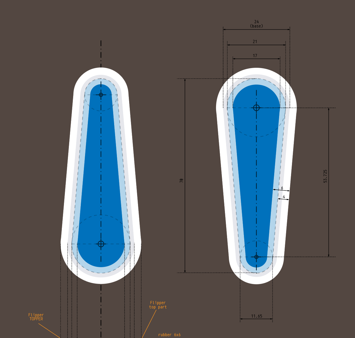
After I designed the dimensions based on some manual tests and some information read on the web, I created a 3D version in Fusion 360 for my printer. Below the final results:
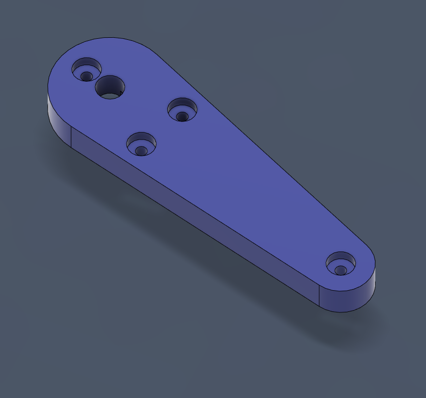
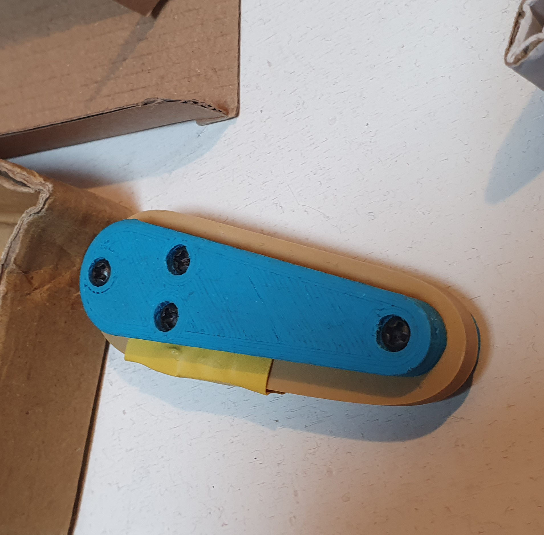
I plan to print on 3D printer also a TOPPER part that will cover holes and screws. It will be glued to the top part. It will have a 3D shape overprinted related to the pinball theme I will choose, some logo or text.
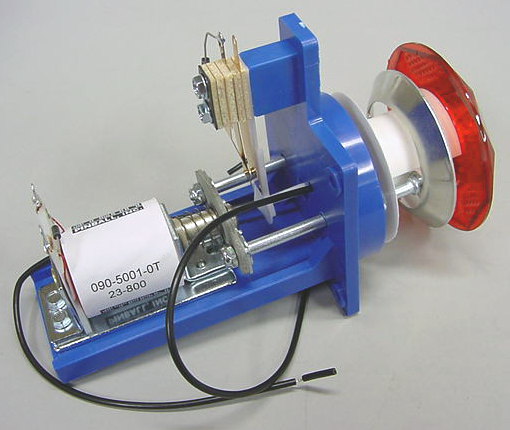
Then I started thinking about the mechanics. Actually even earlier when I started using Fusion 360 for the first time. I was sure I won’t buy original mechanical stuff because of the price. The original mechanics looks like below (right flipper mechanism).
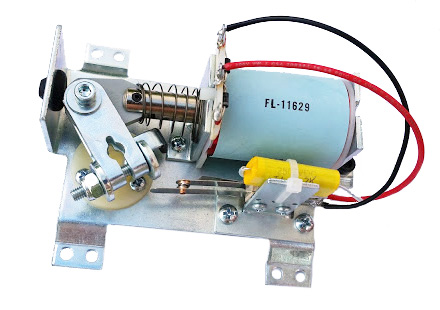
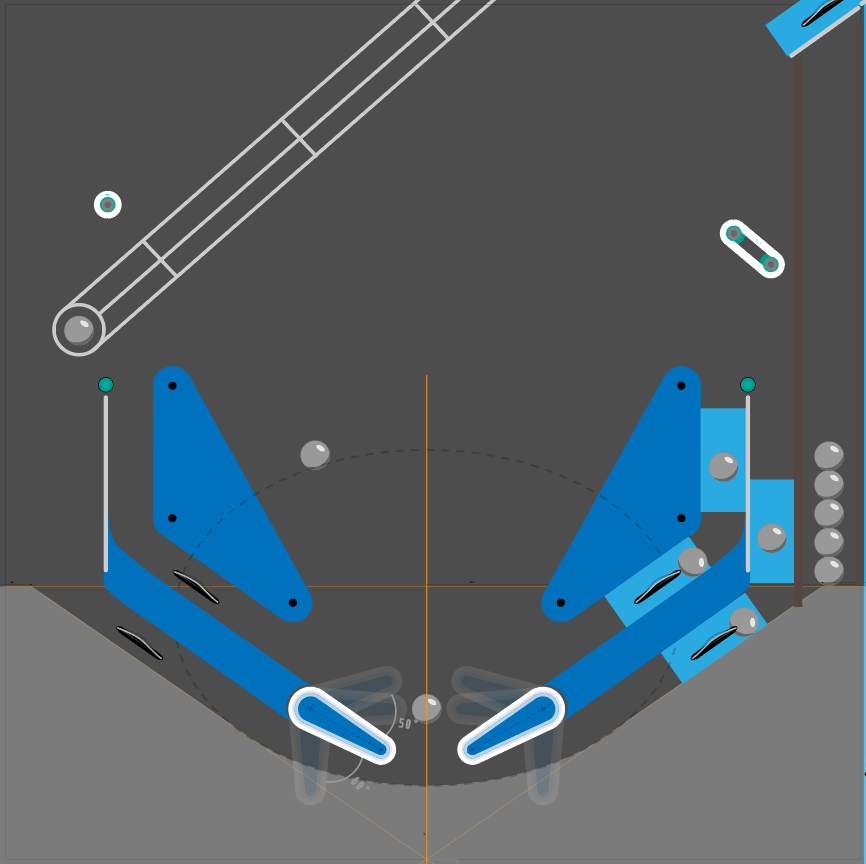
My plan was to create something very similar to this one but built from the materials and parts I have in my workshop. I started again with 2D drawings.
3D Project
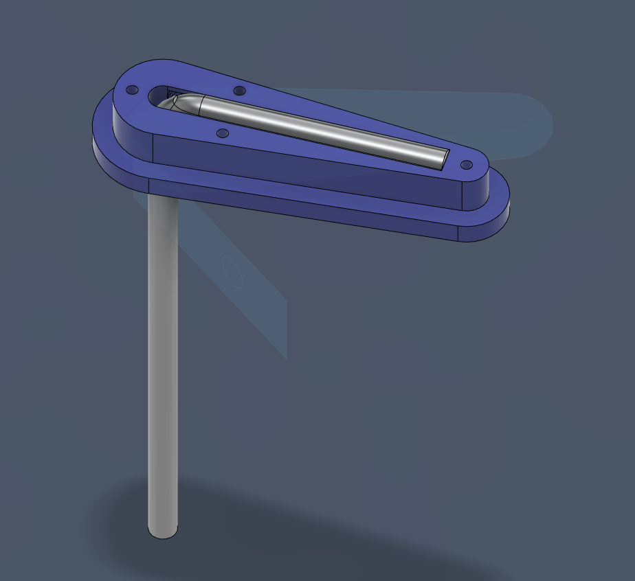
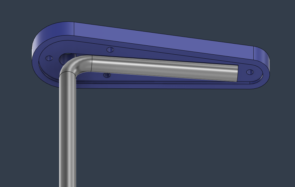
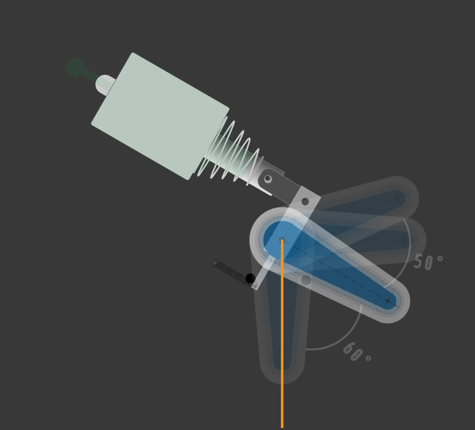
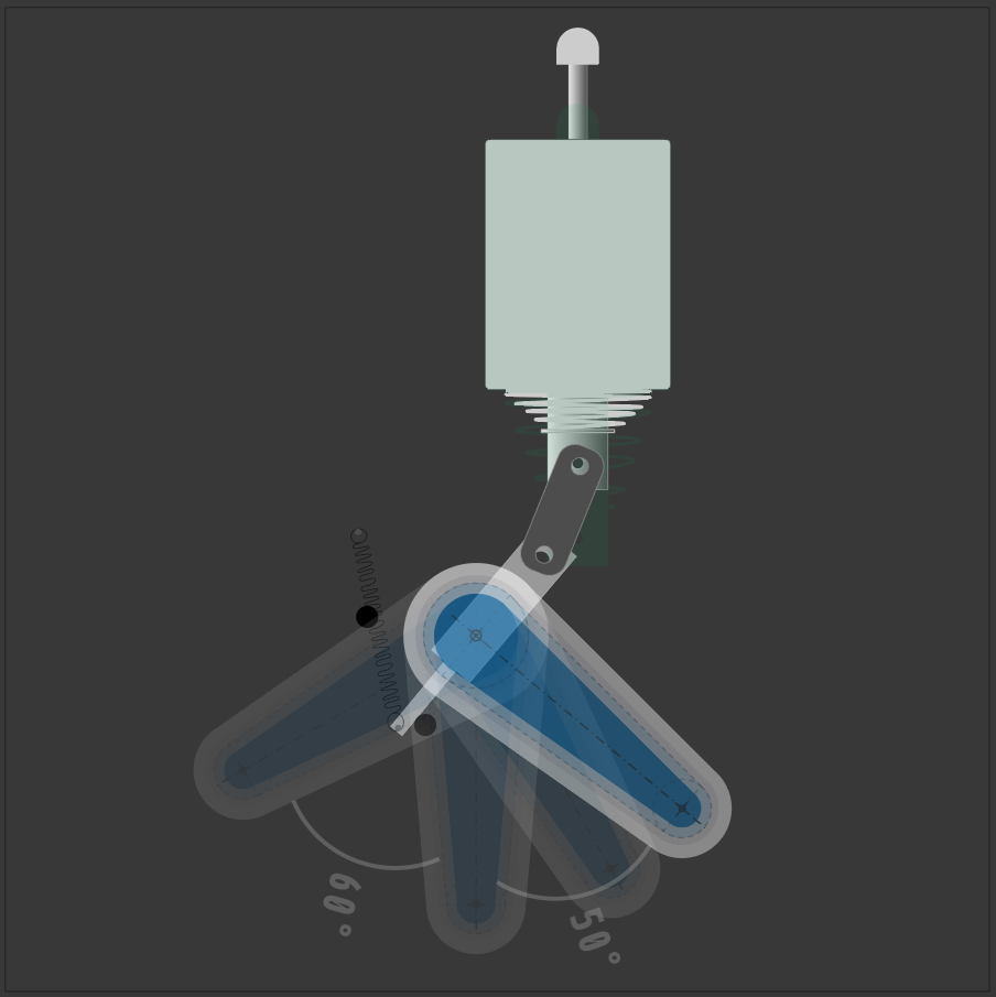
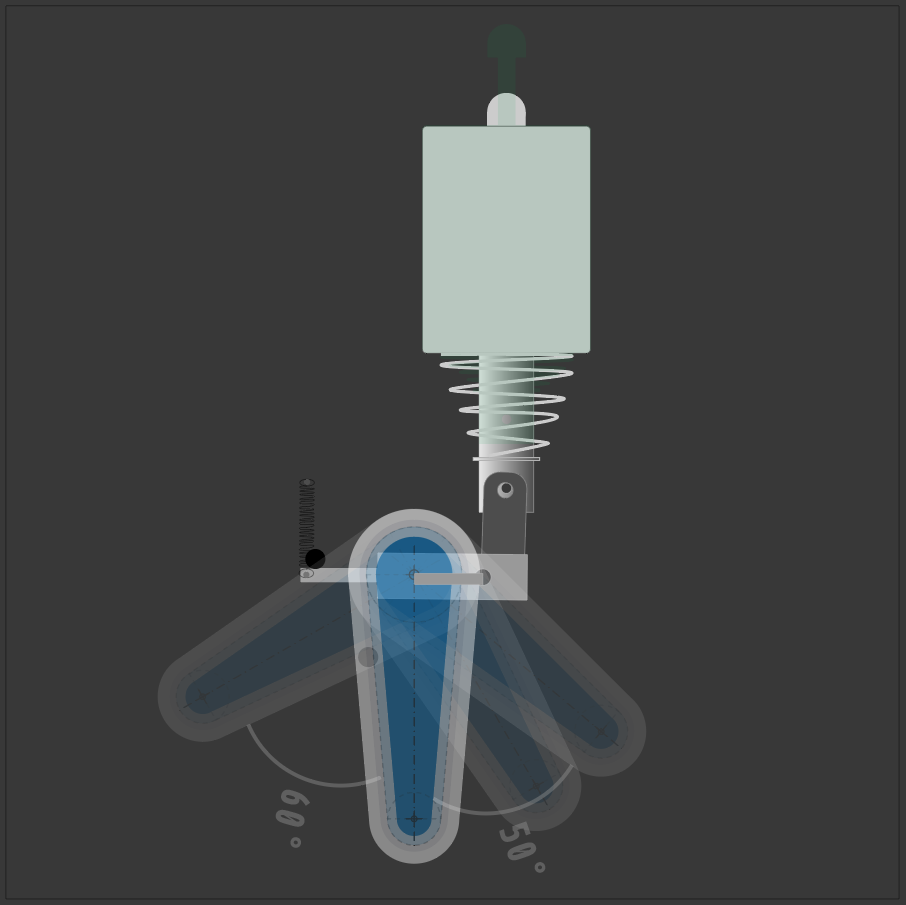
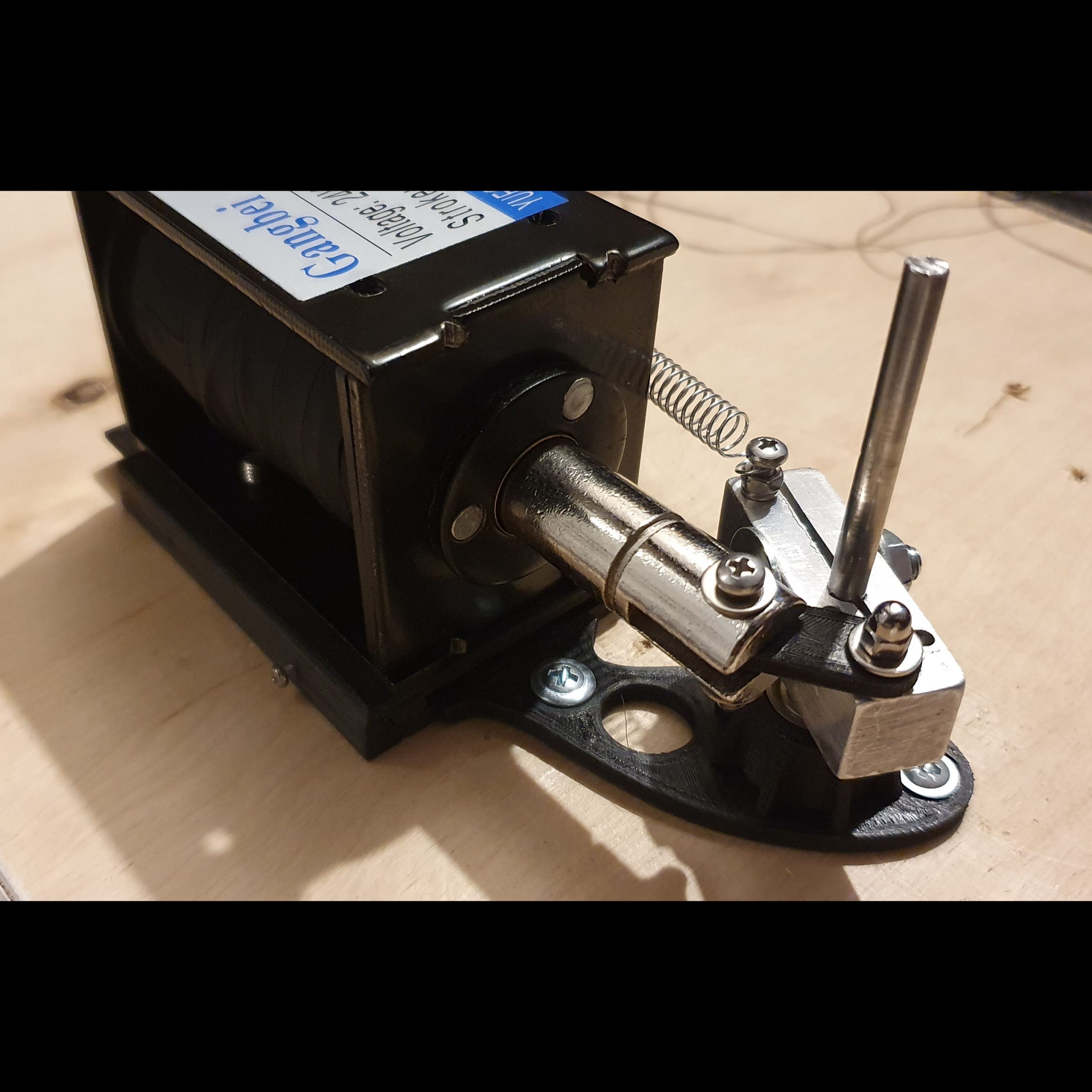
After long research I found a good solenoid candidate for my mechanics, and planned a final mechanics. I also created some prototype to make sure everything will be powerful enough to move the ball. The force of so small flipper (7 cm long) must be powerful enough to bounce the ball so it can trigger some targets and enter the ramps. Below a project in Fusion 360.
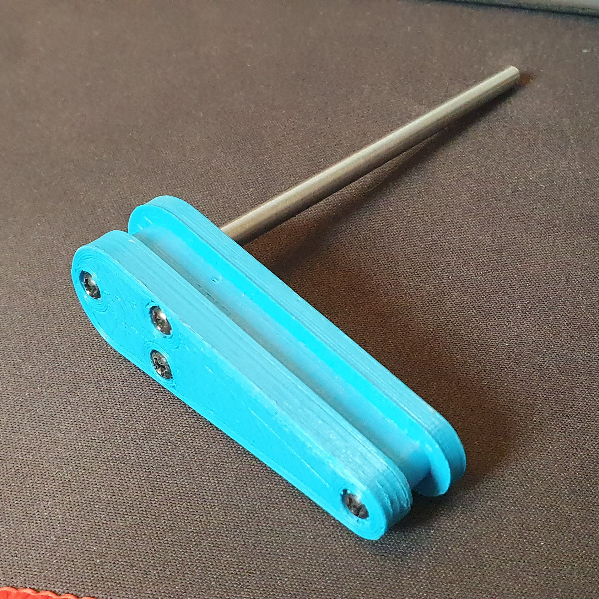
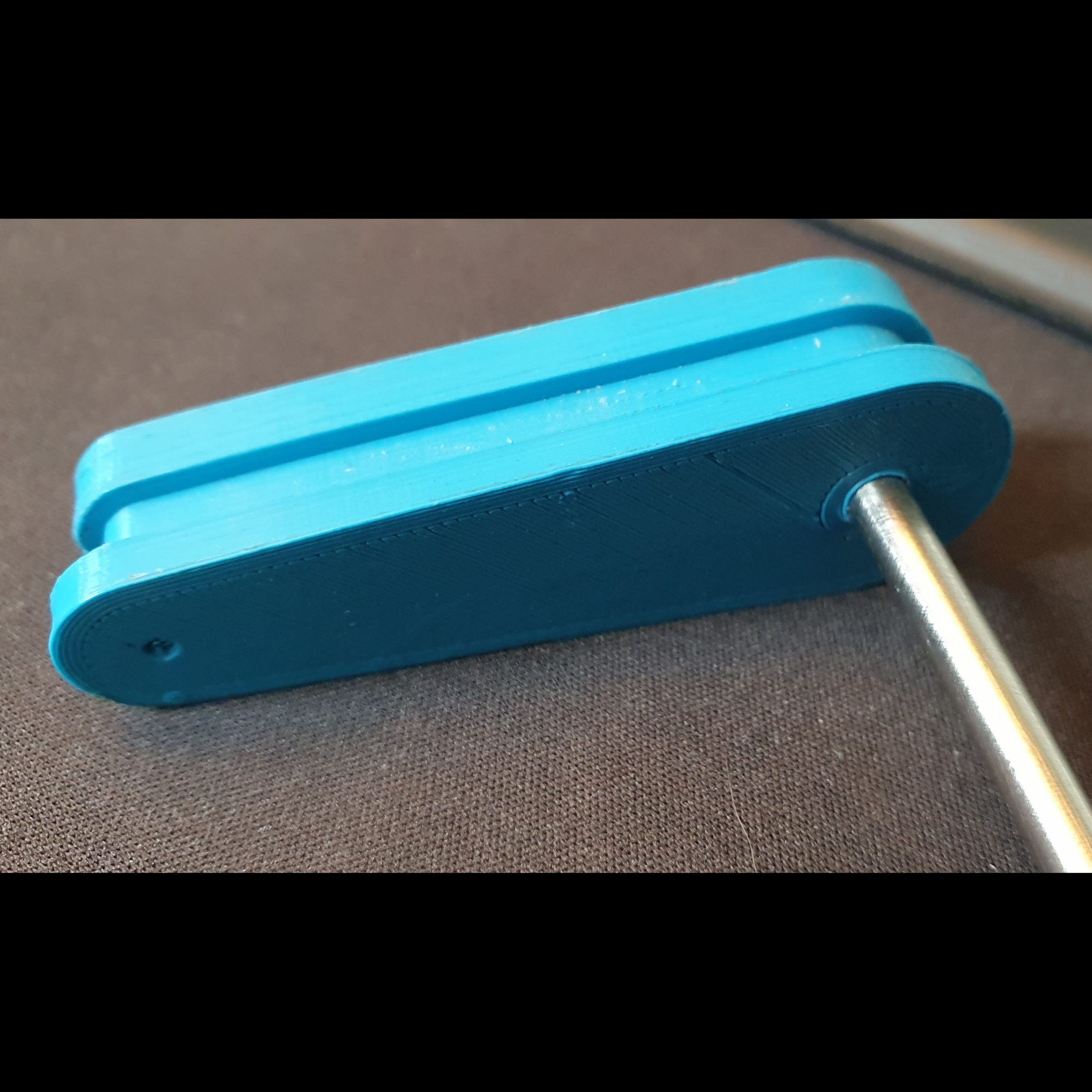
The solenoid I chose is powered by 24V and max current of 10A. The stroke is 20mm which is enough for my mechanics. The flipper core handle visible on a video which is moving the plastic part on the playfield is made of aluminium to make it “softer” and handle the metal core better. The metal flipper axle diameter is 5mm. It is made from steel rod. I used te screw to make it possible to create very tight connection between axle and alu holder. It works very well. Second reason was that i needed something lghter than solid metal. This decreases the force that is needed to move the whole construction by solenoid. Anyway the solenoid is at the end very powerful so the construction must be from other way very solid.
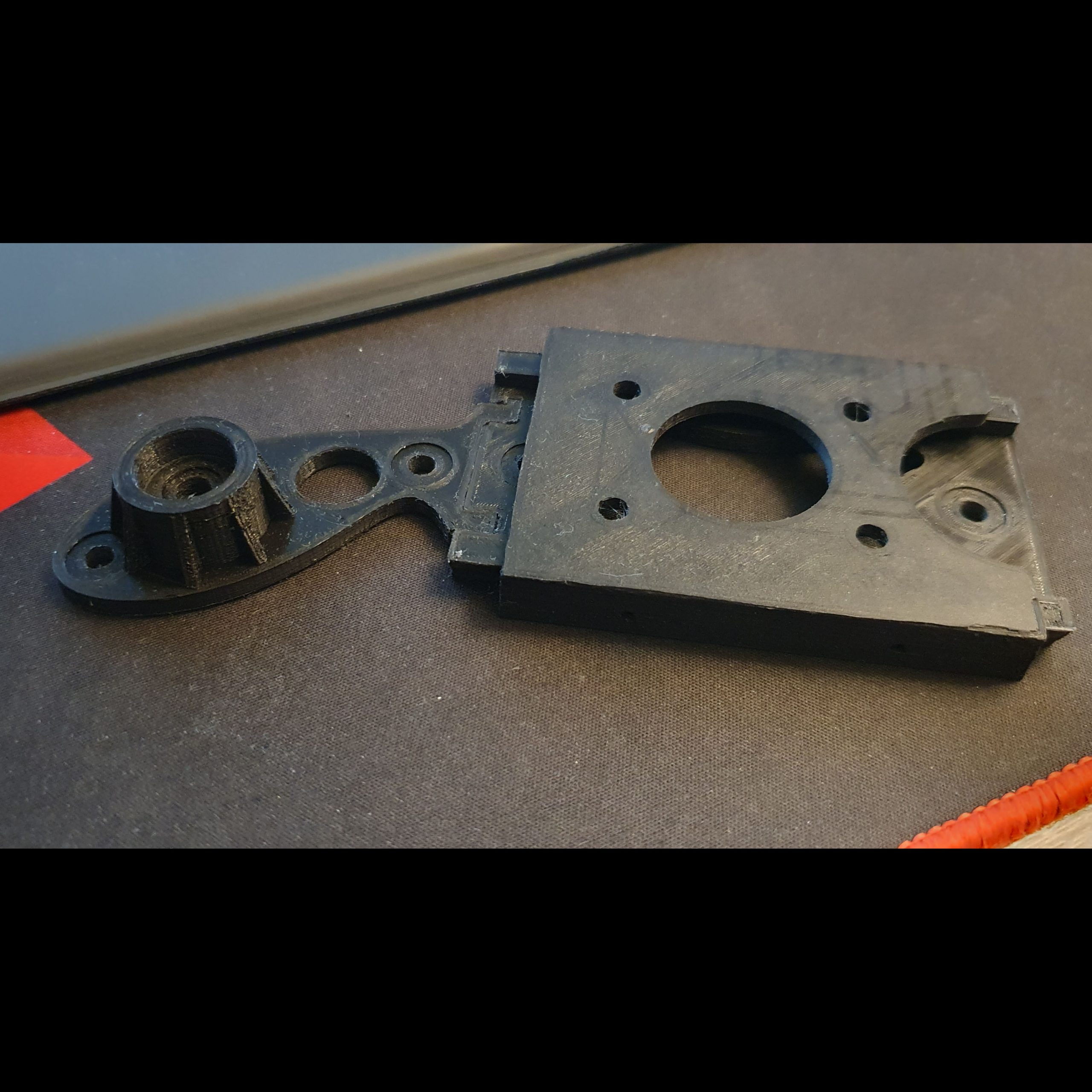
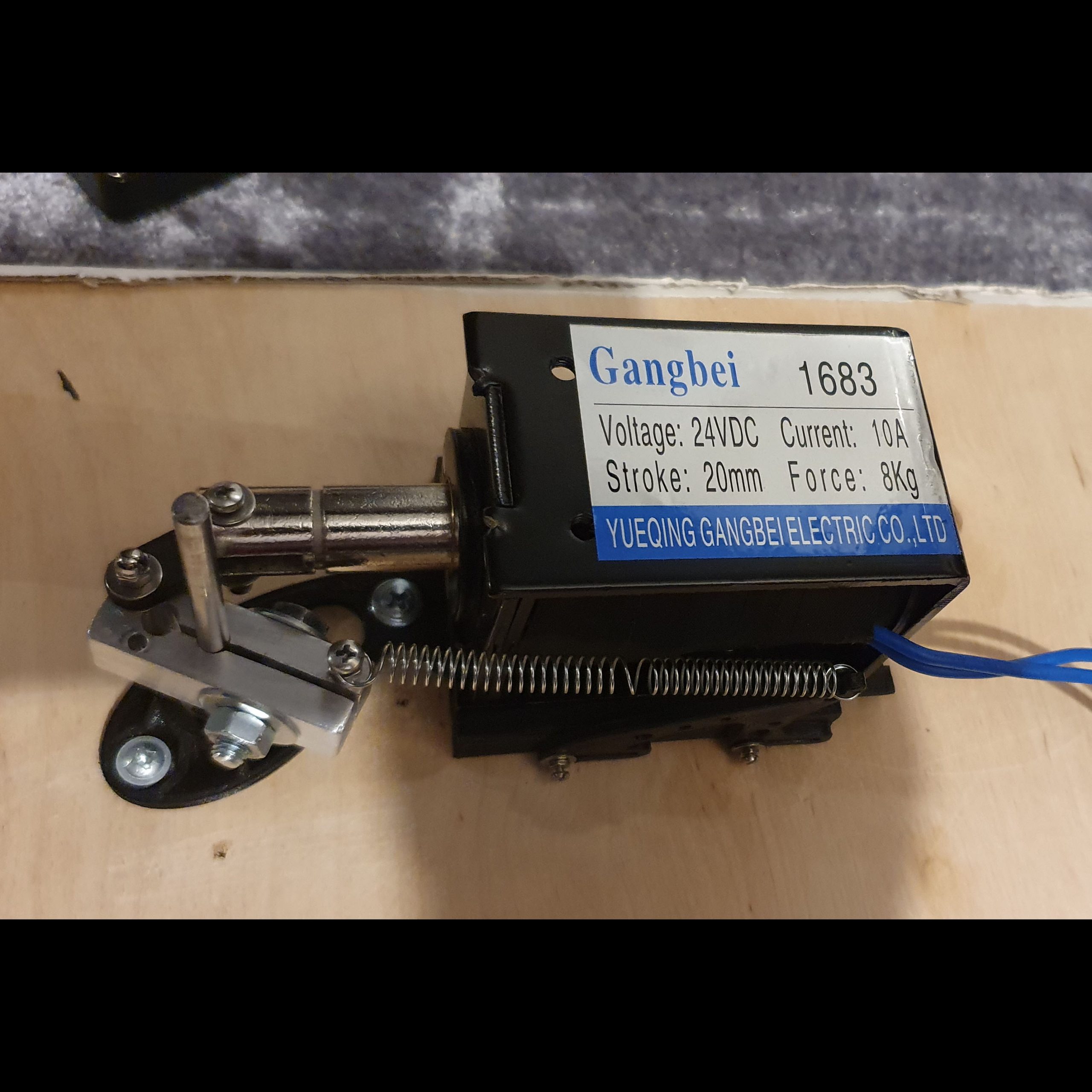
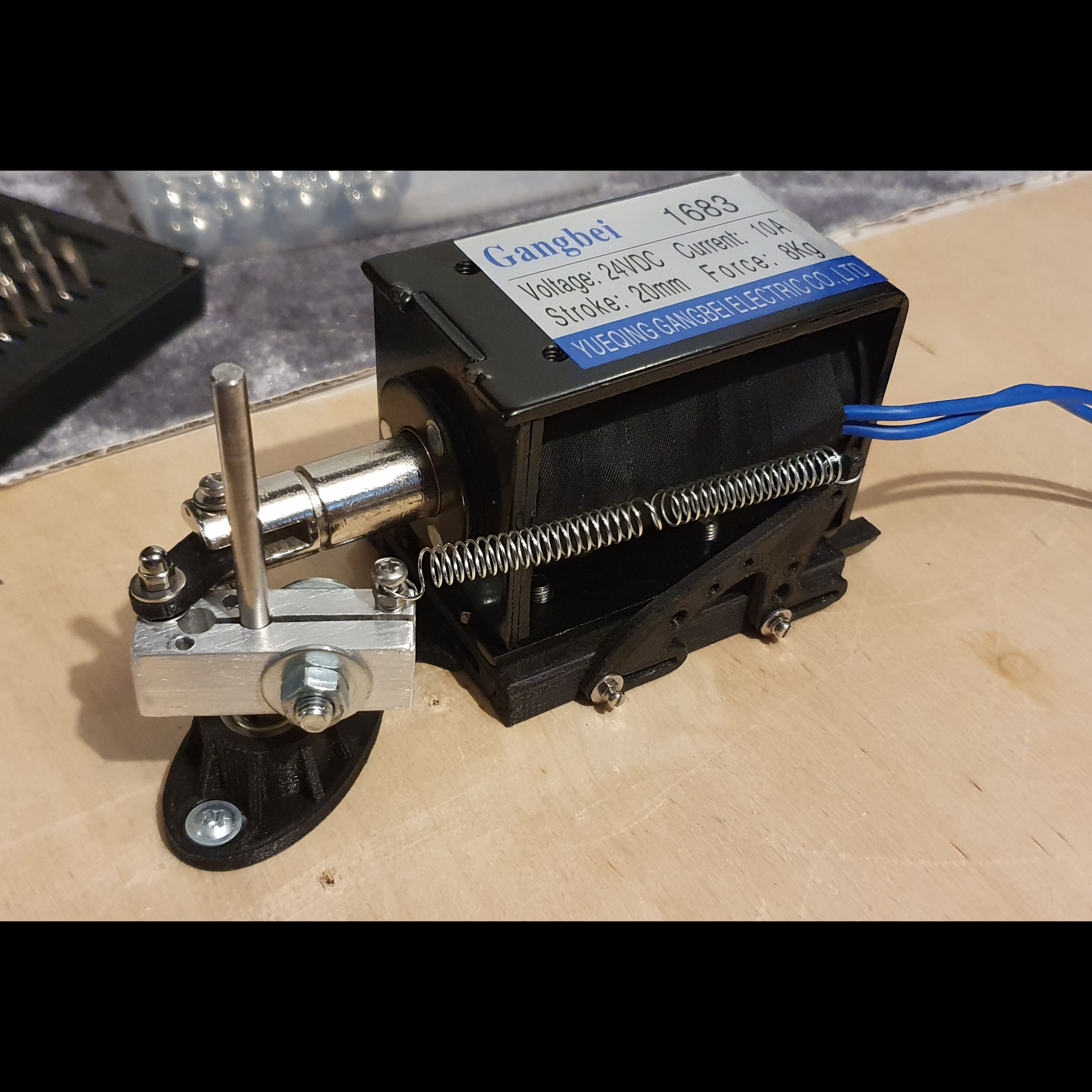
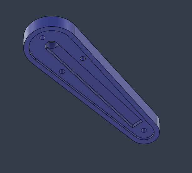
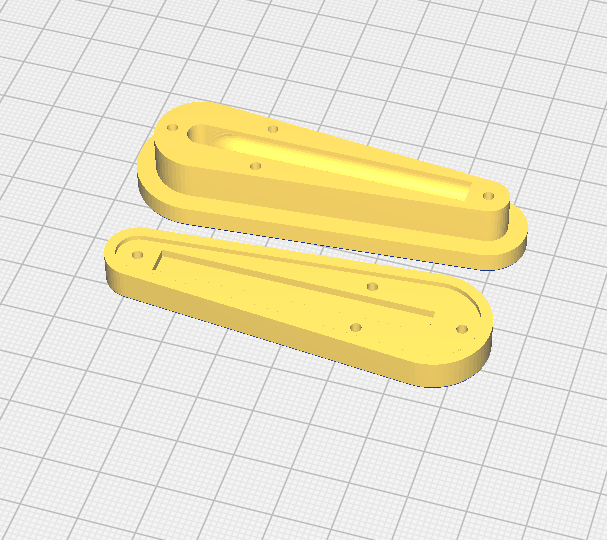
The sliding platform was printed on my Wanhao Duplicator i3. Nothing special but it works OK. I printed two versions of the bearing holder (left and right), second one is a mirror image of the first. Why sliding platform? I noticed that it is very useful to have a more space for adjustment of the distance and force applied to the flipper. This sliding platform gives me that flexibility.
I used long and rather big spring for pulling the solenoid core out. This is because I need a force to quickly move back whole flipper after the button is released. Sometimes user will press the button very frequently and the mechanism must be responsive.
Below you can see how it basically works…
Real play
To test the final force of the flipper I created a small playboard from plywood to check how the ball will be bounced. It works great!
The flipper axle friction is decreased by two bearings: one in plastic holder, second in playfield. This stabilizes also the movement.
Next steps
The flipper mechanics was the most important part for me. Flippers are used by the user and needs more electrical power and let say it is some kind of basic part which must work very well.
I plan to work on next special mechanics for my pinball Pop Bumper. The challenge is not trivial so wish me a luck. The picture below present a standard solution used in pinballs. I plan to create something very close to the original.
I’m able to make some concessions when designing because my pinball ball will be smaller (19 mm instead of 27 mm) and don’t need so huge force to bump the ball. Probably my next post will shade some light on that topic 😉